Kossel XL 3D printer.
Table of contents
Intro
Since childhood, I had been struggling with the lack of precision in my own hands. And the issue isn’t really about me; it’s more about the biomechanical nature of humans – if you’ve ever tried to create something with your own hands, you know the results are rarely perfect. Our muscles can’t control our limbs with sufficient accuracy to ensure repeatability; our eyes are not perfect either. There are two paths to overcome these difficulties: either extensively develop your own skills (achieving some success but still constrained by the body’s imperfections) or delegate these problems to machines. I chose the latter path.
There are two fundamental approaches to make a custom part:
- You can take a piece of material and remove the excess to shape the object. This is the route CNC mills follow.
- You can do the opposite – not remove anything but simply grow the desired object layer by layer from material. This is the realm of 3D printers.
When 3D printers first appeared, I thought they were just toys. At that time, I had more sympathy for CNC mills. It seemed the advantages were clear: CNC mills can work with virtually any material, even metals. And from metals, you can create serious things – strong, lightweight. What can printers do, after all? They’re limited to plastic as a material, and the parts are built layer by layer. Who guarantees that the layers will hold together properly?
I was mistaken. Jumping ahead a bit, I can say the following: printed parts are quite strong (even when they are mostly hollow – solid only on the outer surfaces, with a lattice structure inside).
However, when I began building this printer, I still believed it would be a mere toy, not particularly useful. And I started building it mostly out of boredom.
For reasons that no longer seem convincing enough to list here, I chose non-orthogonal kinematics. I didn’t want to design from scratch, so I picked an open-source design as a foundation – the Kossel XL.
Frame


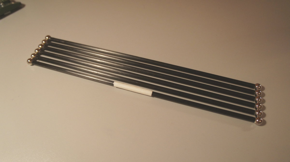
Rods
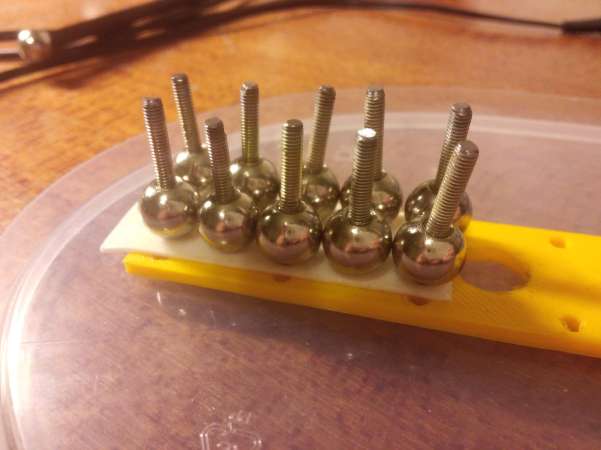
I had some bad luck with carbon tubes for the rods. The diameter of the holes in them is 3 mm, while the ball joints have M4 threads. I decided to use trimmed M3 screws as connectors. I had to epoxy them into the ball joints:
Afterward, I selected the longest carbon tube and made the first rod:

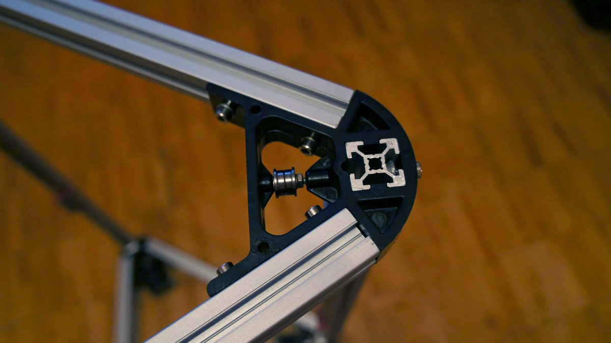
Once the first rod was ready, I needed to create a template to manufacture the rest of them (to ensure that all rods have the same length). I 3D printed a couple of fixtures for this purpose:
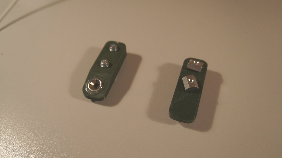
I secured the fixtures onto the profile, using the first rod as a guide:
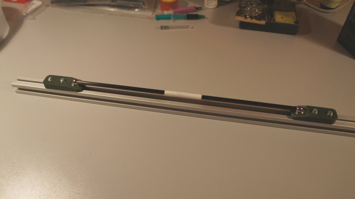
Using this template, I then glued the remaining rods:
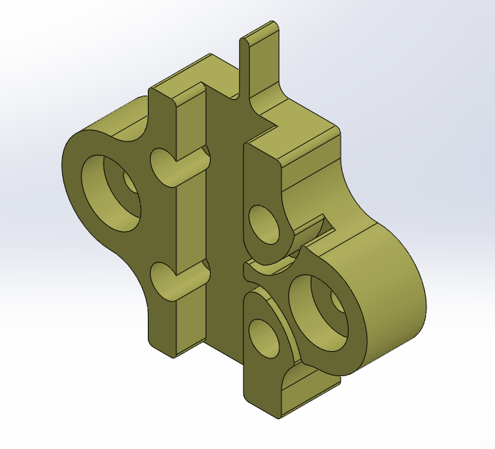
Carriages and effector
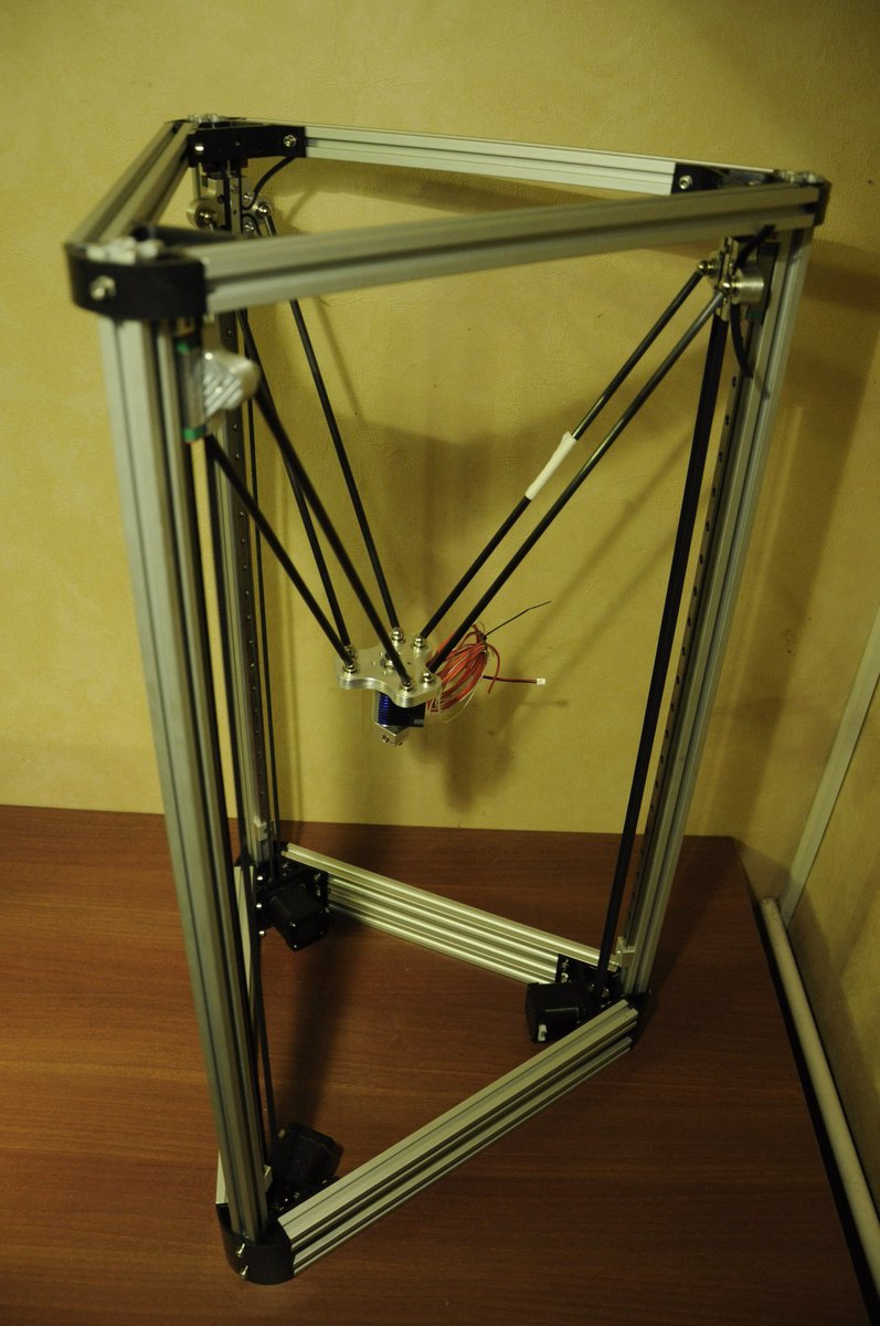
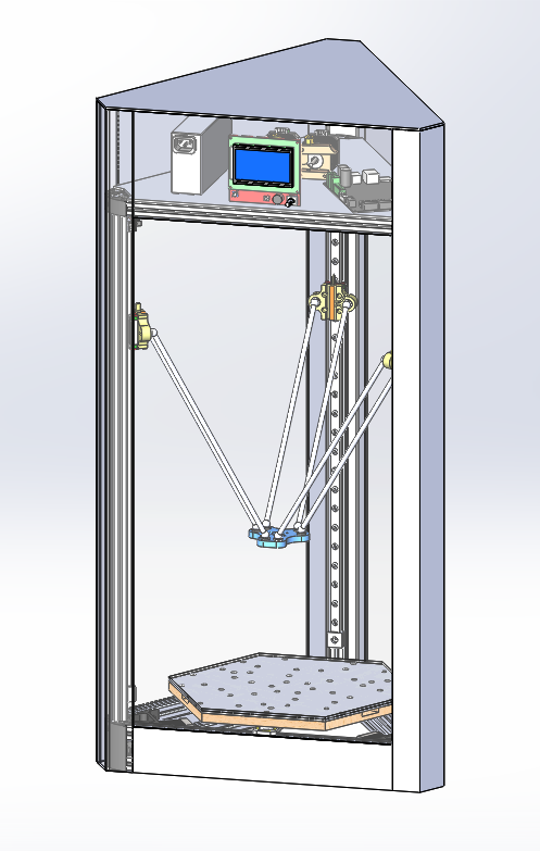
For convenience, I have created a complete printer 3D model in SolidWorks:

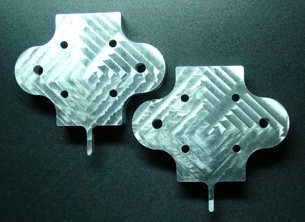
I have designed 3D models of the effector and carriages:
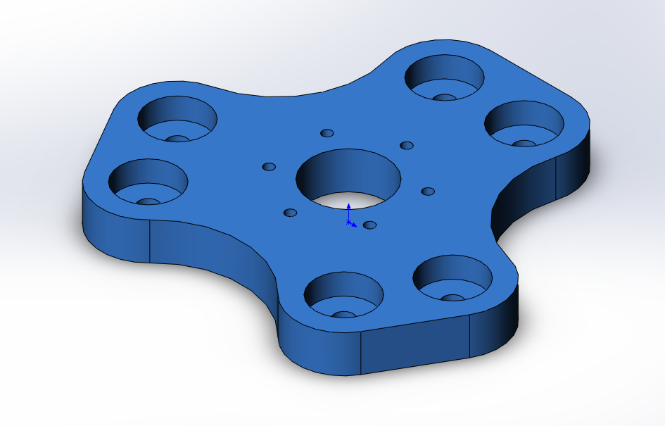
They have been manufactured using aluminum:

First-time assembly


Heatbed
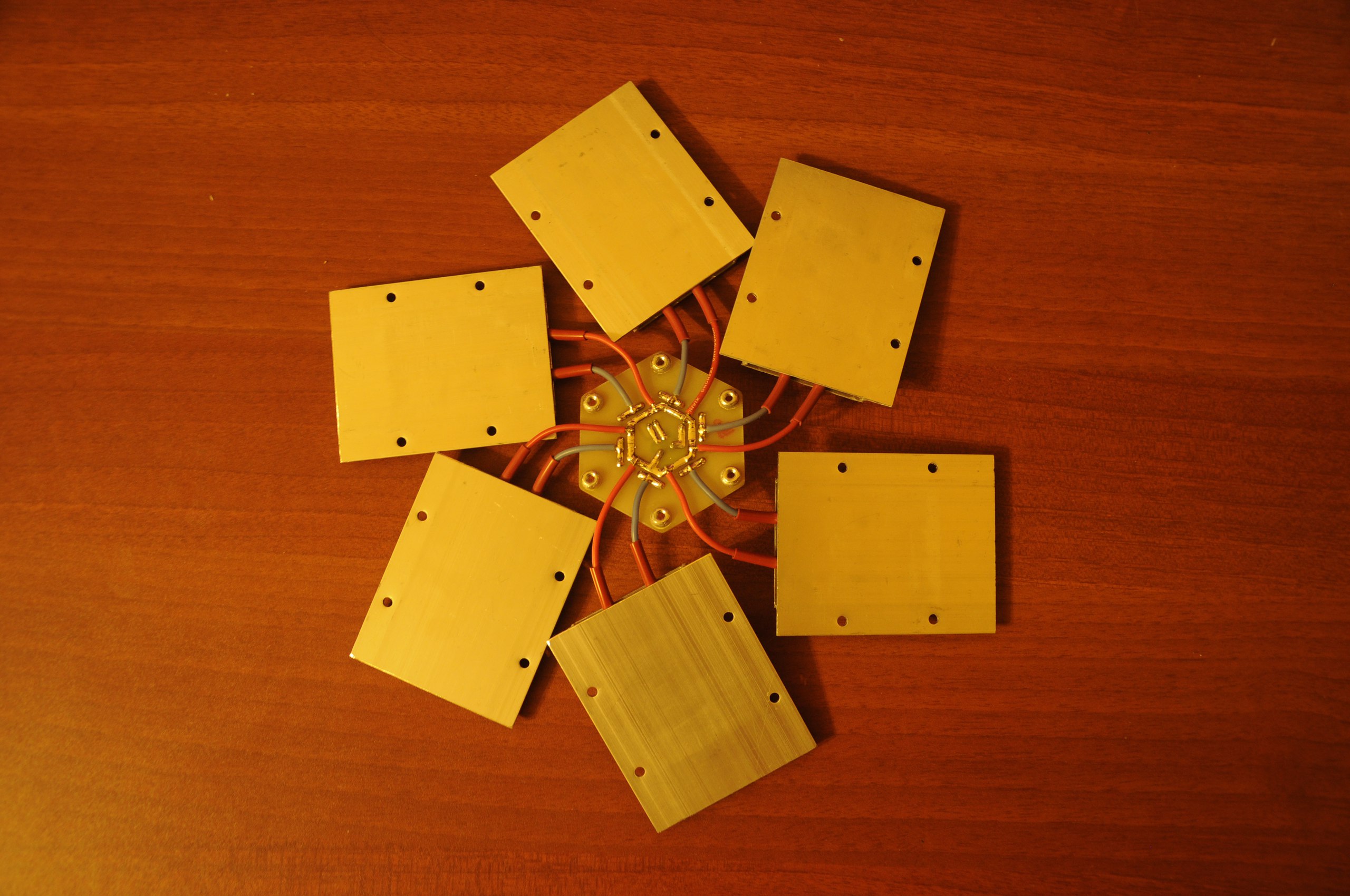
I failed to find a suitable heated bed for sale (the requirements were: sufficient power and 220 volts), so I decided to make it myself. I used PTC heaters, here is the specification:
- Operating temperature - 200°C (regulated by a thyristor power controller).
- Power - 200W.
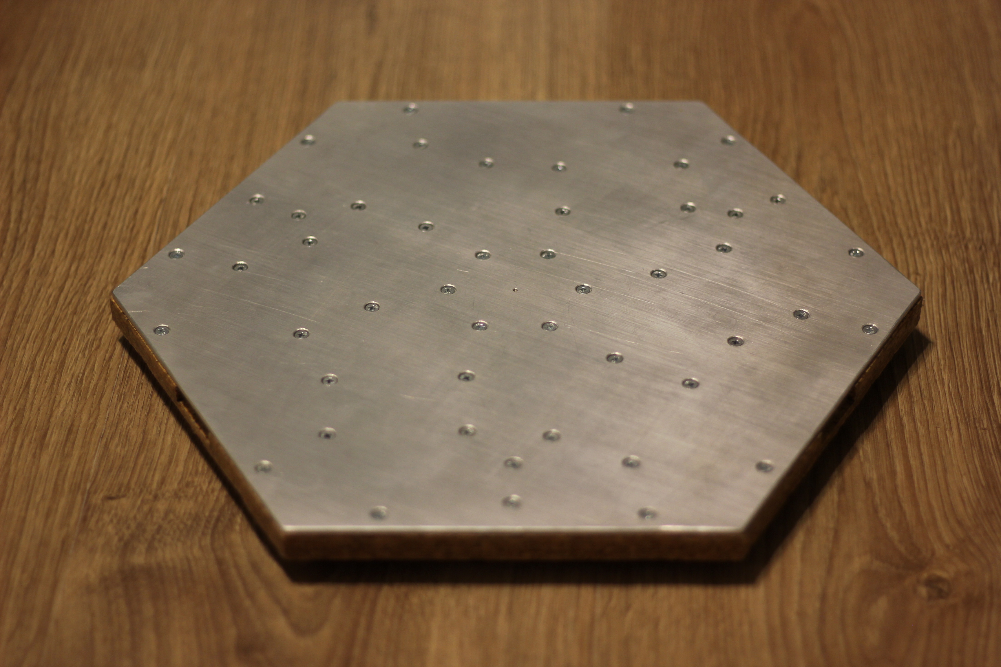
To begin with, the positioning of the heating elements needed to be determined. The objective was to achieve optimal heating uniformity. Thermal modeling was performed in SolidWorks. As a result, the following configuration was arrived at, ensuring a minimal temperature variation of only a few degrees Celsius:

Next, a 3D model was created in SolidWorks:
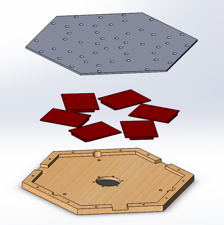
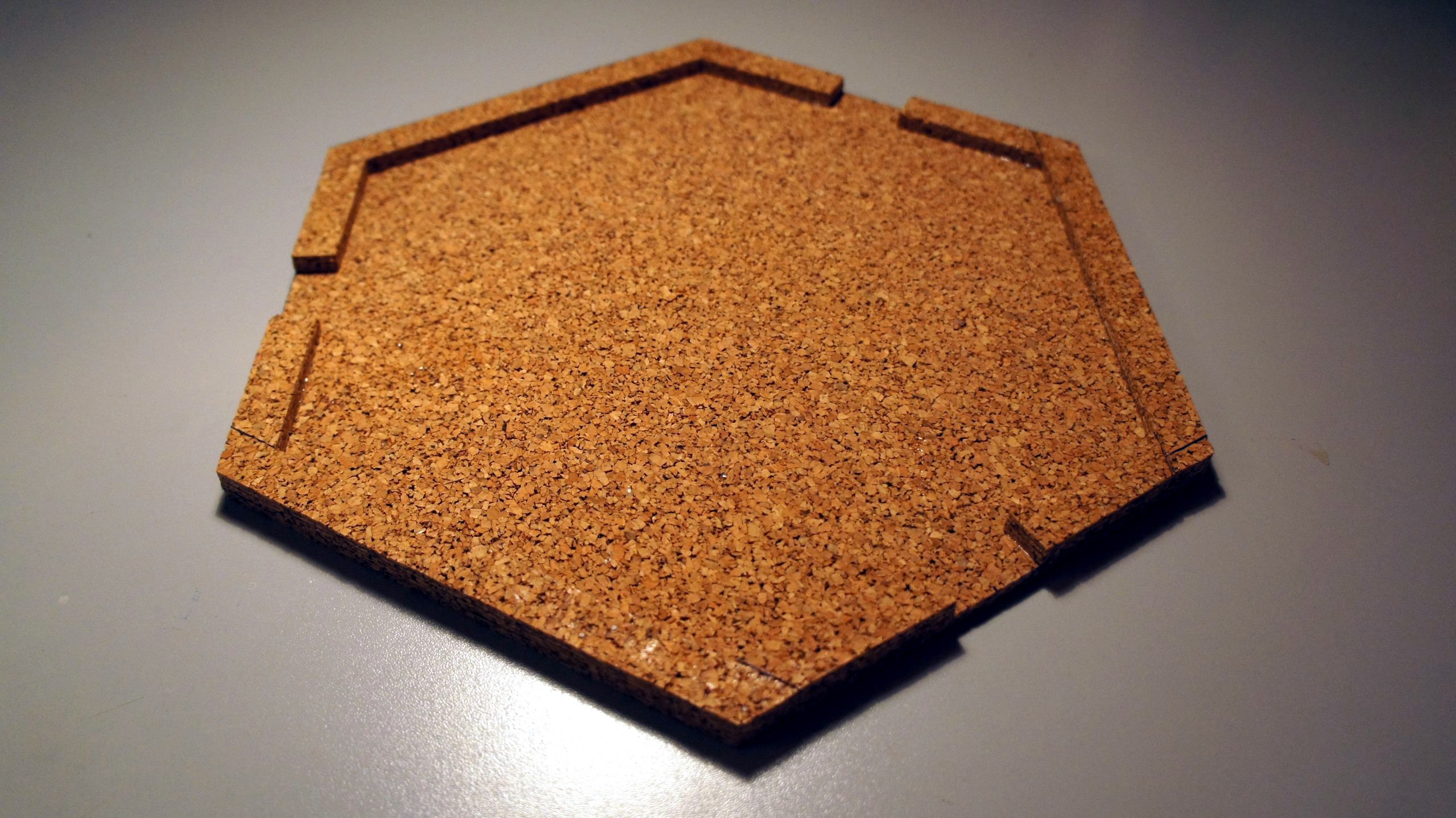
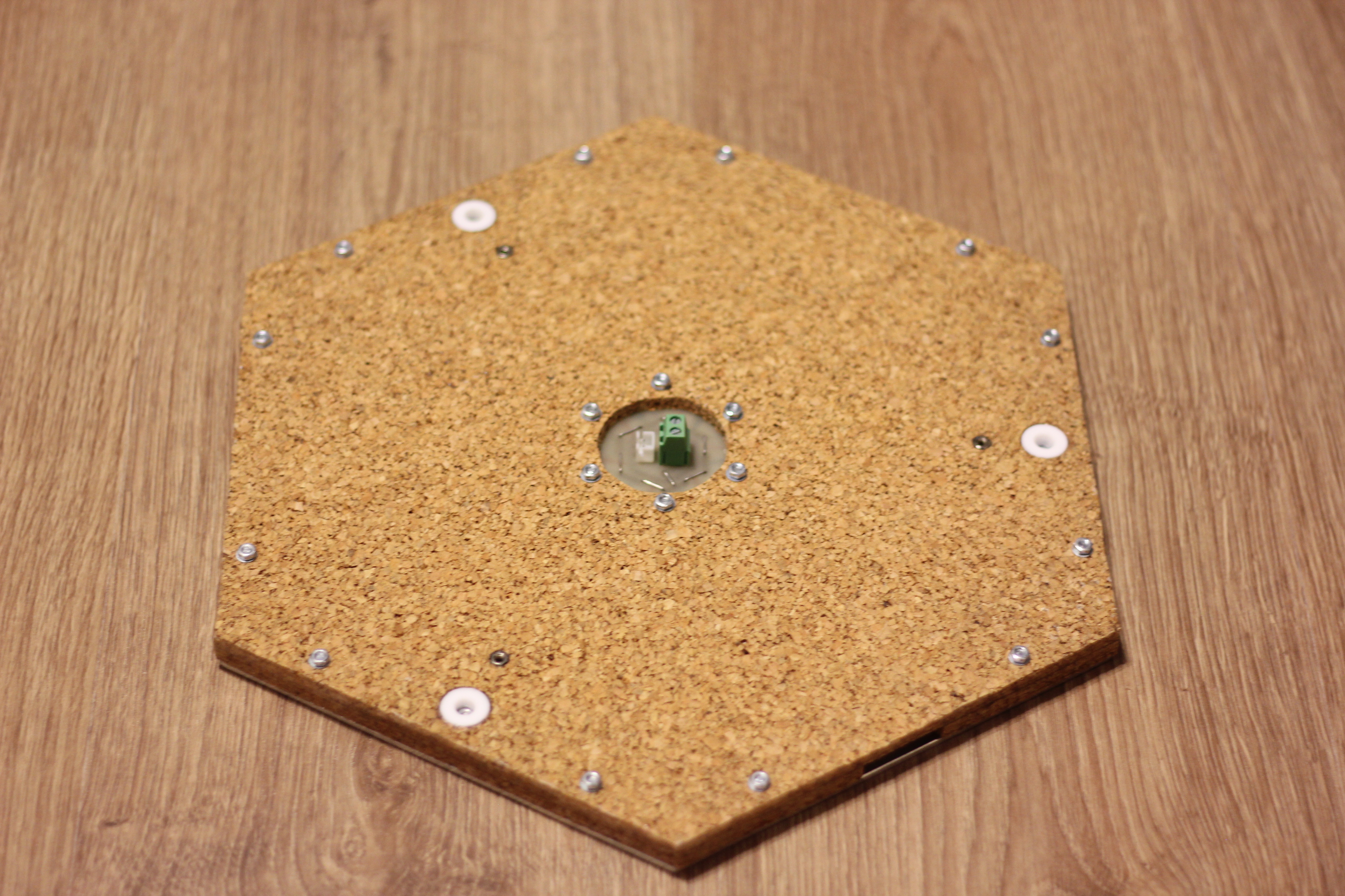
To further reduce heating time and prevent heat loss, a cork enclosure was installed underneath (constructed with multiple layers of cork approximately 2 mm thick, bonded together with high-temperature silicone sealant):
Here is the PCB through which the heating elements can be connected to the power controller (also featuring a connector for the thermistor):
Here is the final result:
Autoleveling
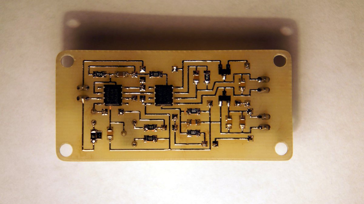
A sensor was needed to detect the moment when the nozzle touches the heatbed. Among the existing solutions, I only liked the idea of using force-sensitive resistors (FSR), but they were quite expensive. A friend of mine suggested an alternative – piezoelectric elements, which were super affordable on AliExpress. Further research also revealed similar projects, so I decided not to reinvent the wheel and blatantly borrowed the circuit from there. After some modifications – replacing the op-amps with cheaper equivalents (almost any rail-to-rail op-amp that can run on the required voltage will work) and enhancing input protection – the circuit took on the following form:

Assembled:
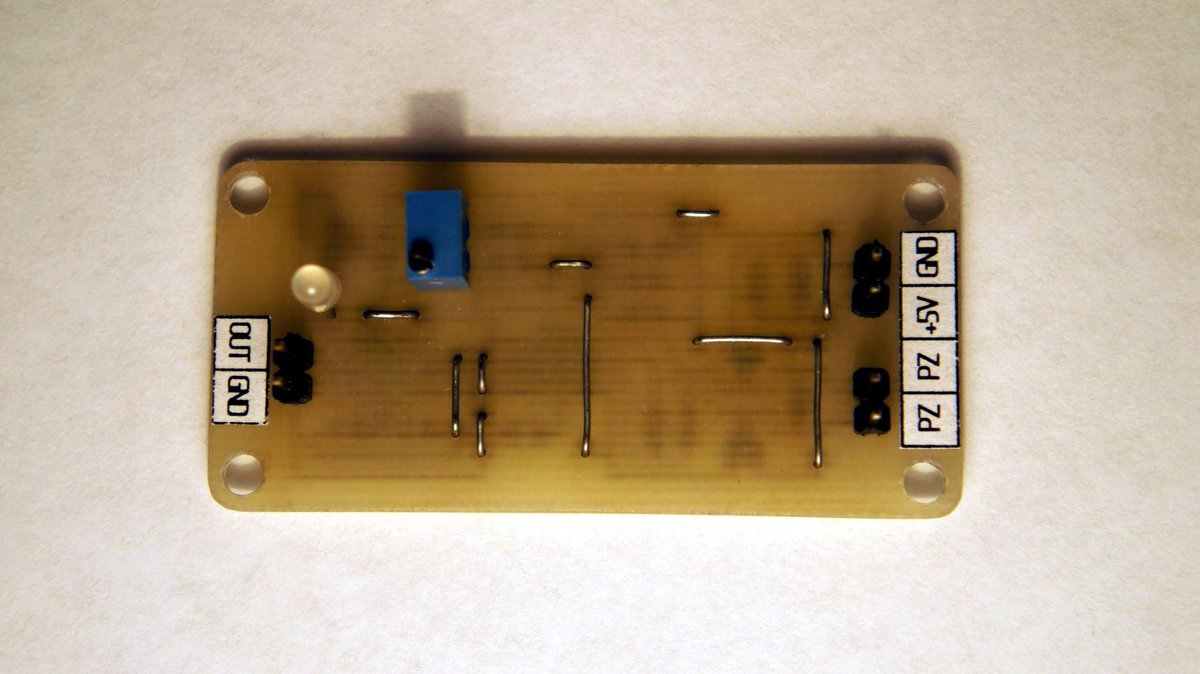
A short test video (focus your attention on the green LED located on the PCB on the right):
What’s next?
Just when everything was almost ready, an unpleasant issue emerged: the frame that had been constructed posed difficulty in attaching the enclosure (thermal chamber). In my attempts to resolve this problem, I created several prototypes in SolidWorks, but none of them satisfied me for various reasons. Here they are:
Version 1.1: the standard frame with a thermal chamber made of bent aluminium mounted on top, with the electronics mounted above:
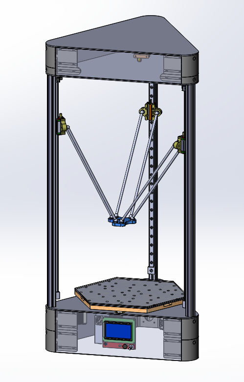
Version 1.2: an attempt to position the electronics underneath using standard frame components:
Version 1.3: the standard frame with a thermal chamber constructed from separate aluminum plates (instead of bending):
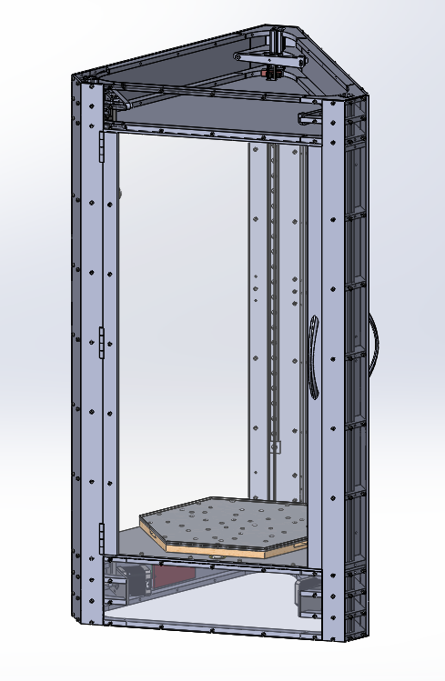
Version 1.4: a frame entirely made from bent steel sheets, eliminating the use of aluminum profiles:

Version 1.5: the standard frame with ABS 3D-printed corner components for the enclosure inspired by the idea from here:

Unfortunately, the ideal solution that would satisfy me has yet to emerge (by the way, as of writing this article, I’m considering another approach). However, if it does eventually come together, this article will certainly have a continuation.
Outro
Unfortunately, this project was never fully completed. 3D printers are rapidly evolving, so while I was pondering the design of the thermal chamber, many aspects of this project became outdated. However, undoubtedly, this project holds great value as it provided me with a wealth of knowledge and new experience.