3DConnexion SpaceMouse Wireless Ergonomic.
Table of contents
- What is 3DConnexion?
- Intro
- Prototyping
- 3D scanning
- Version 0
- Solving version 0 issues
- Version 1
- Final renders
What is 3DConnexion?
A brief description of the device that will be discussed further:
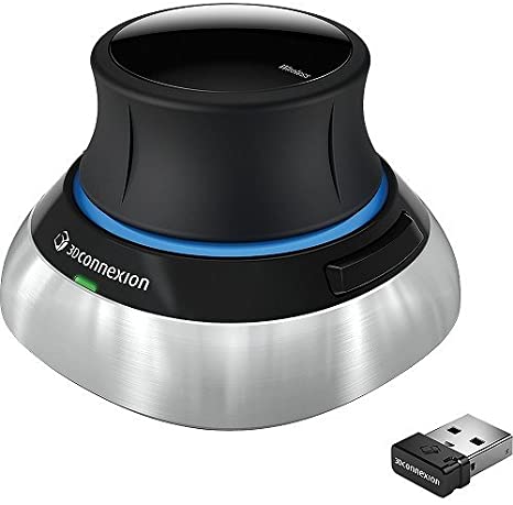
The 3D manipulator (or 3D mouse) by 3Dconnexion is a device designed for three-dimensional positioning using a ball or joystick (6 degrees of freedom). It is used for working with 3D design systems or applications that require control over an objects’ movements within a virtual space.
For instance, in 3D modeling, it’s often necessary to adjust the camera’s position (to work on different parts of the model). The camera has six degrees of freedom: three linear ones (which determine the camera’s position in the global coordinate system) and three rotational ones (representing the camera’s rotation angles). A six-axis manipulator enables control over all these parameters:

The most interesting aspect is that this manipulator allows you to control all degrees of freedom of the camera simultaneously. Compared to using just a mouse and keyboard, where you need to perform a series of actions to move the camera from one place to another and rotate it, a six-axis manipulator enables you to achieve the same result in a single motion. This is highly convenient and time-saving. Downside: getting used to this method of control takes a bit of time (several days or so).
Intro
Buying a brand new device from a store was a bit expensive (plus, I wasn’t entirely sure if I really needed it), so I periodically checked a local online flea market. After some time, luck was on my side, and I managed to purchase the device. Immediately, the following issues were identified:
-
It turned out that the SoftTouch coating applied to the working part of the manipulator deteriorates over time and becomes sticky. The solution was straightforward: armed with isopropyl alcohol, cotton pads and wipes, I simply removed it. The plastic underneath was also quite pleasant to touch, and there were no problems due to the removal of the coating.
-
The metallic base of the device, covered with something like decorative chrome, had some scratches. Of course, this problem didn’t hinder the device’s functionality in any way, but it was a constant eyesore and source of annoyance. I decided to tackle this issue with a more drastic solution, which will be discussed in the following paragraphs.
It’s worth saying that I’m a fan of vertical mice, like the ones depicted below:

Regular mice, when used extensively, can lead to issues like carpal tunnel syndrome, whereas vertical mice help alleviate these problems:

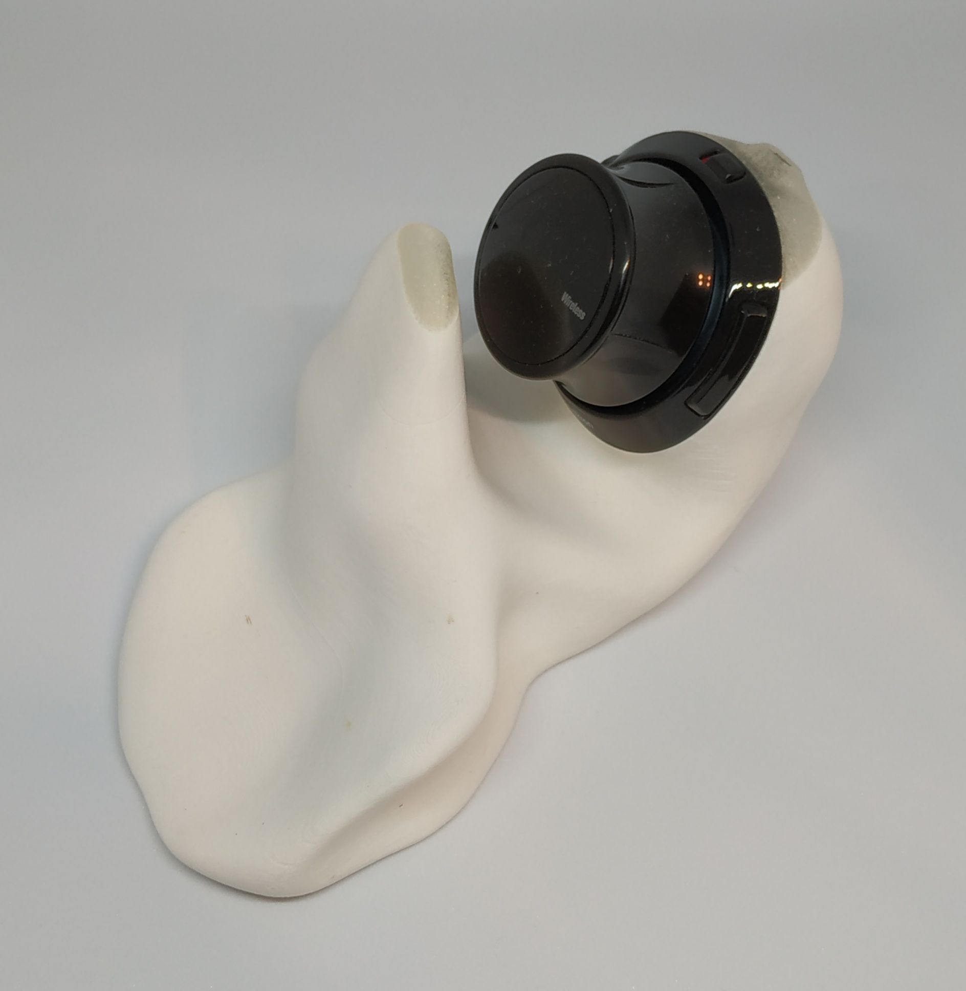
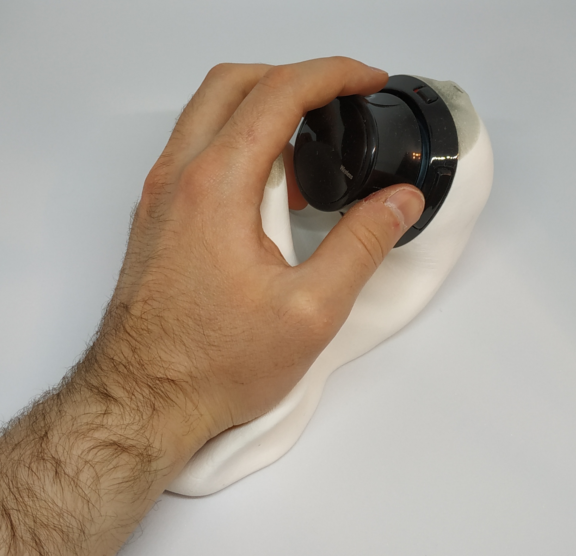
Since the original design of the six-axis manipulator resembled a regular mouse in terms of poor ergonomics, a decision was made to create a new base for the manipulator, which would allow the hand to be in a comfortable position while working.
Prototyping
Alright, how to create the new base then? There were no doubts about the method of manufacturing – given the anticipated complex geometry, 3D printing was the way to go. But how to make the 3D model? Basically, there were two options:
-
Make a 3D model, print it, test how comfortable the hand rests on it. Afterward, adjust the model, print it again, and test it once more… This process could involve numerous iterations.
-
Take a soft material like clay or plasticine and try to sculpt a base prototype from it. Since the material is pliable, you can modify the model and test various options on the fly. Finally, digitize the prototype using a 3D scanner.
The second option seemed more enjoyable, so it was chosen. It was decided to use plasticine, but the regular one wasn’t suitable because it’s quite challenging to work with – it’s pretty rigid at room temperature, requiring preheating, and then it gets messy. A more suitable option was found – JOVI children’s plasticine, which remains pliable even at room temperature, making it a pleasure to work with:

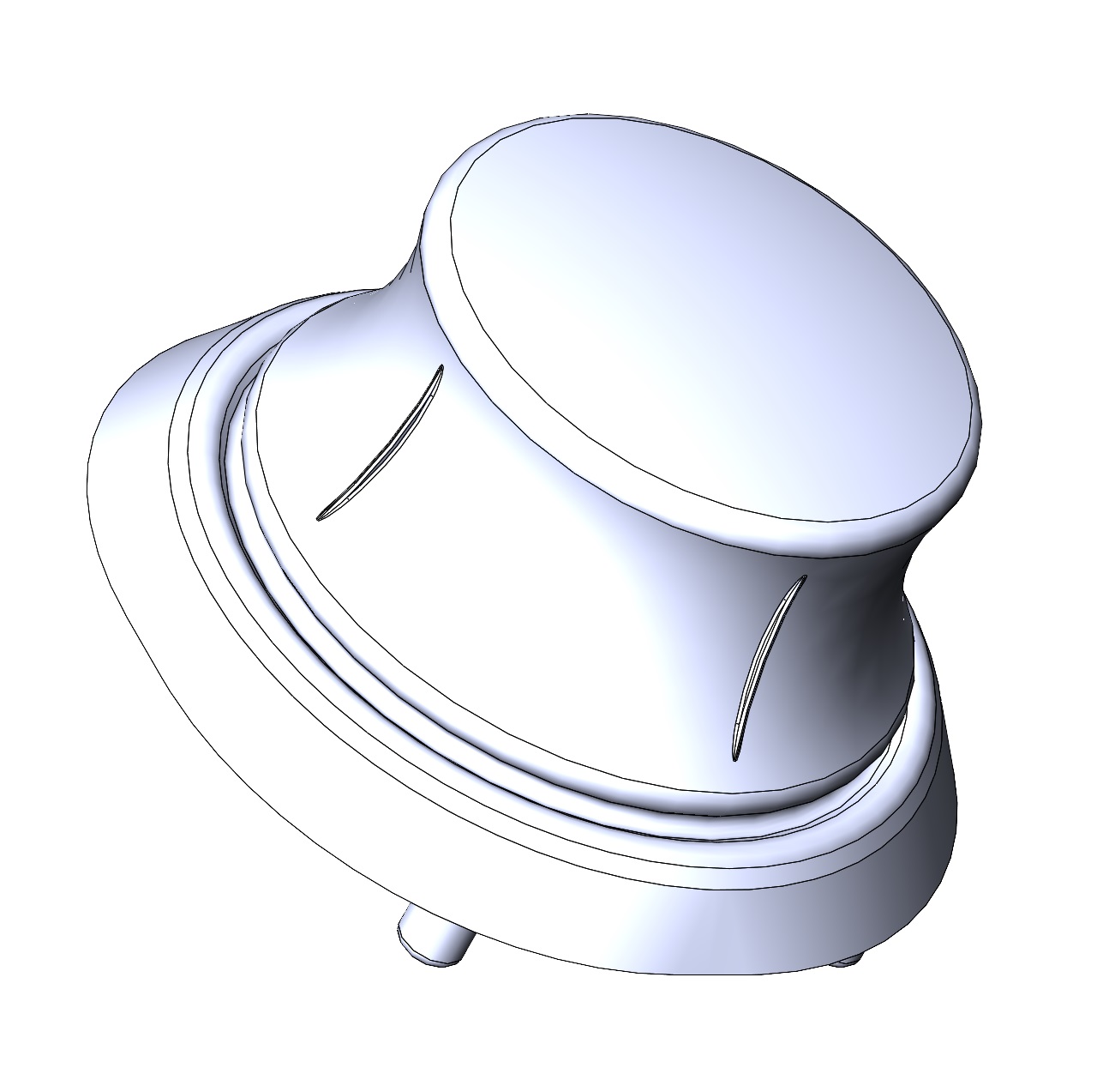
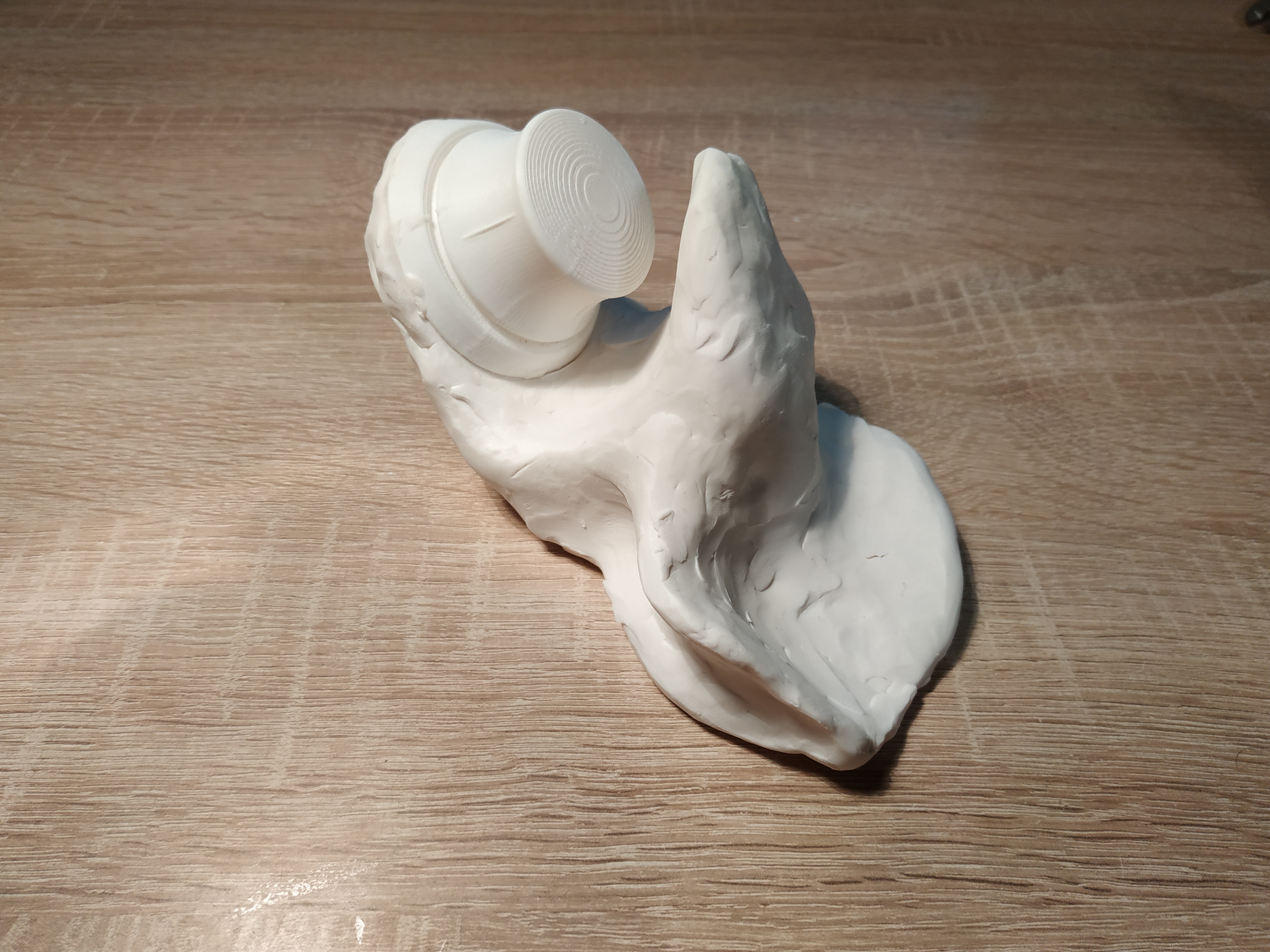
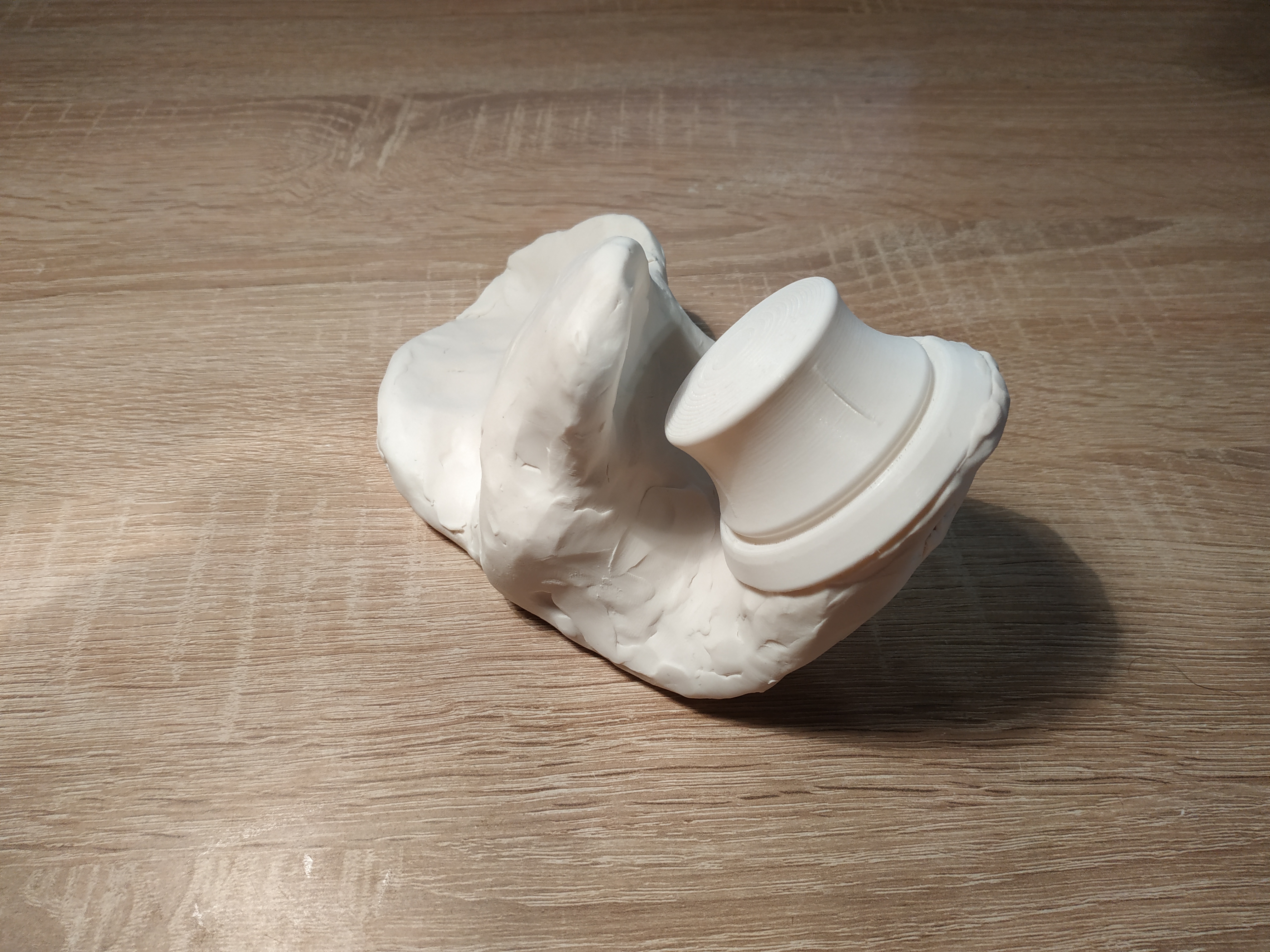
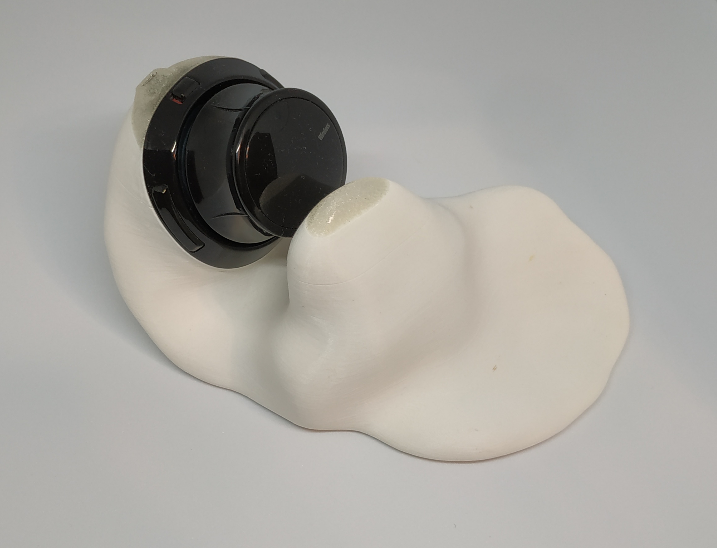
Additionally, in order to avoid getting plasticine on the manipulator parts, a prototype of the knob was 3D printed:
This was the current result:

3D Scanning
Now, it’s necessary to digitize the model. For this purpose, a budget-level 3D scanner, the Ciclop 3D, was purchased:

Setting up this device turned out to be a separate hard challenge, worthy of its own dedicated article. Furthermore, it was discovered that the plasticine model was too large to be scanned in its entirety; it had to be cut in half, scanning the halves, and then stitching them together in a 3D editing software (utilizing Meshmixer):
Halves:
The stitched halves:
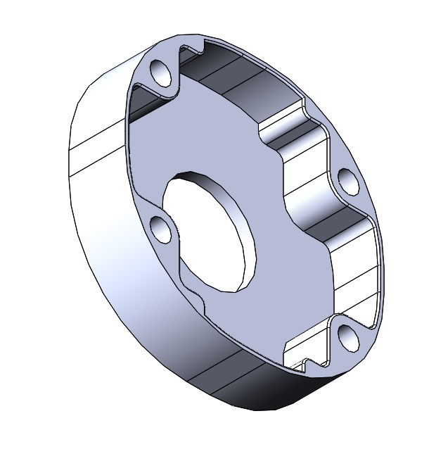
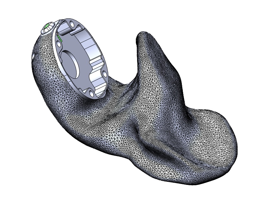
Creating a 3D model for the seating area of the manipulator’s knob:
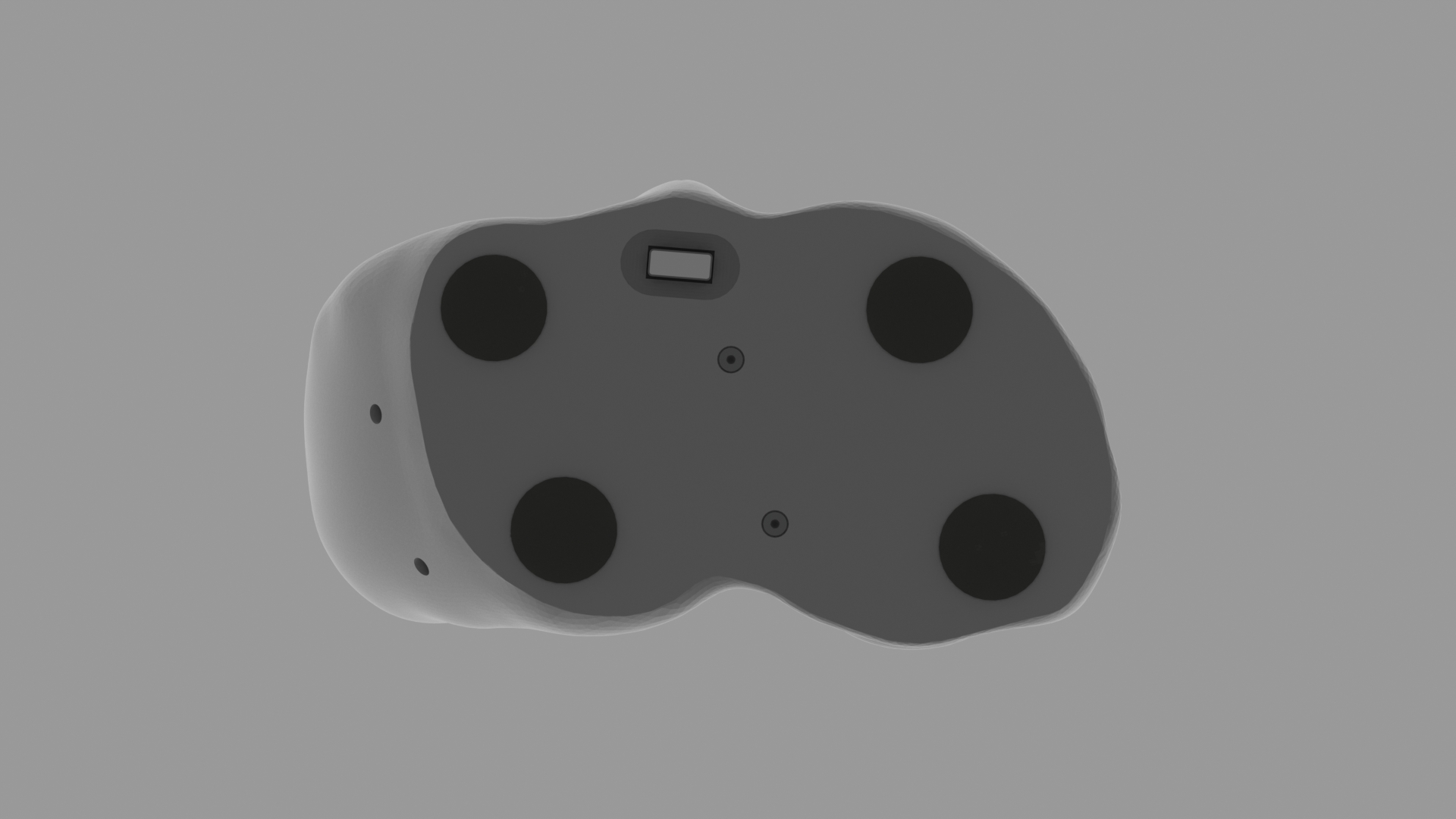
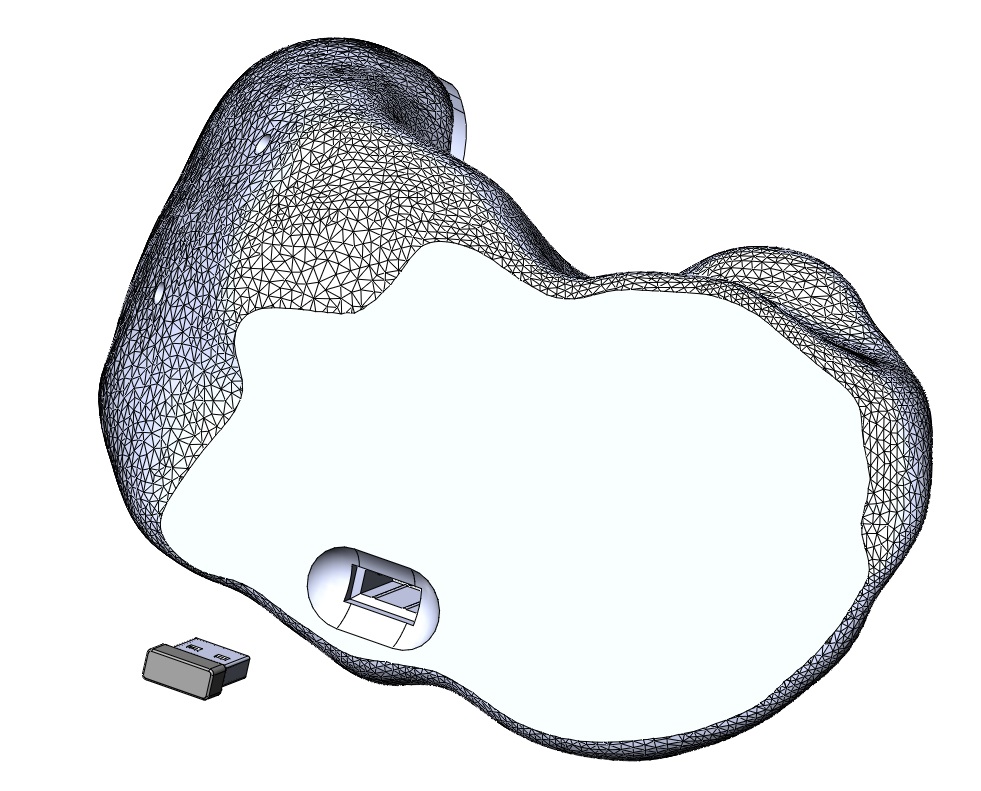
Next, we import the base mesh into SolidWorks, and add the other components: the seating area for the knob, the USB connector hole, and the docking spot for the USB dongle. Here is the result:


Next, we export the resulting 3D model back to STL, move to Meshmixer for final refinement (replacing sharp transitions in geometry with smooth blends). The final result is:
Version 0
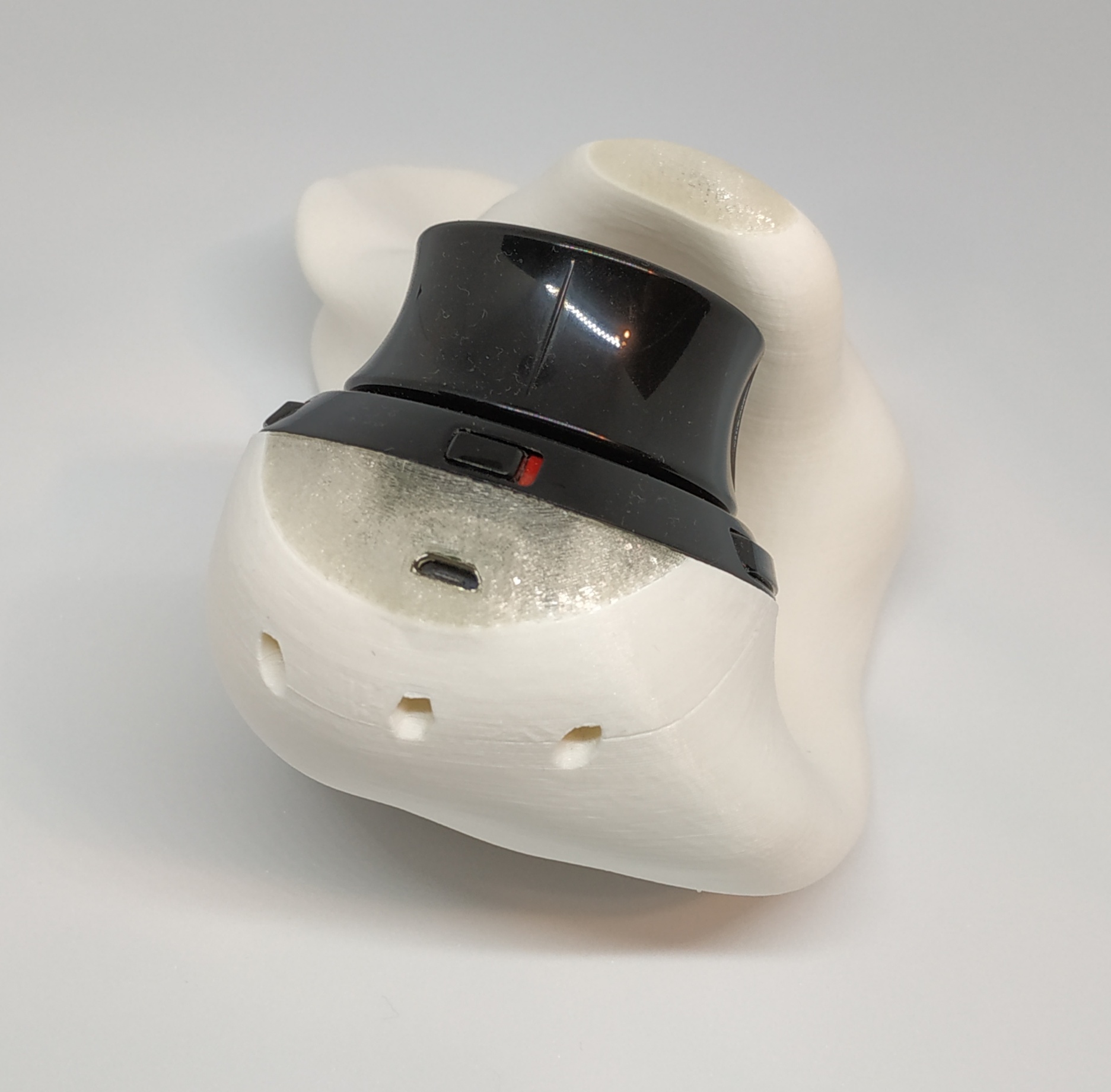
Unfortunately, the white plastic ran out during printing, so a small part of the base had to be completed using transparent plastic :)

Version 0 issues:
-
The base turned out to be too lightweight, necessitating the use of double-sided tape to affix it to the table in order to use the device. This issue needs to be addressed somehow. For instance, one approach could be to add weight to the base by making it hollow and filling it with a mixture of epoxy resin and metal shavings.
-
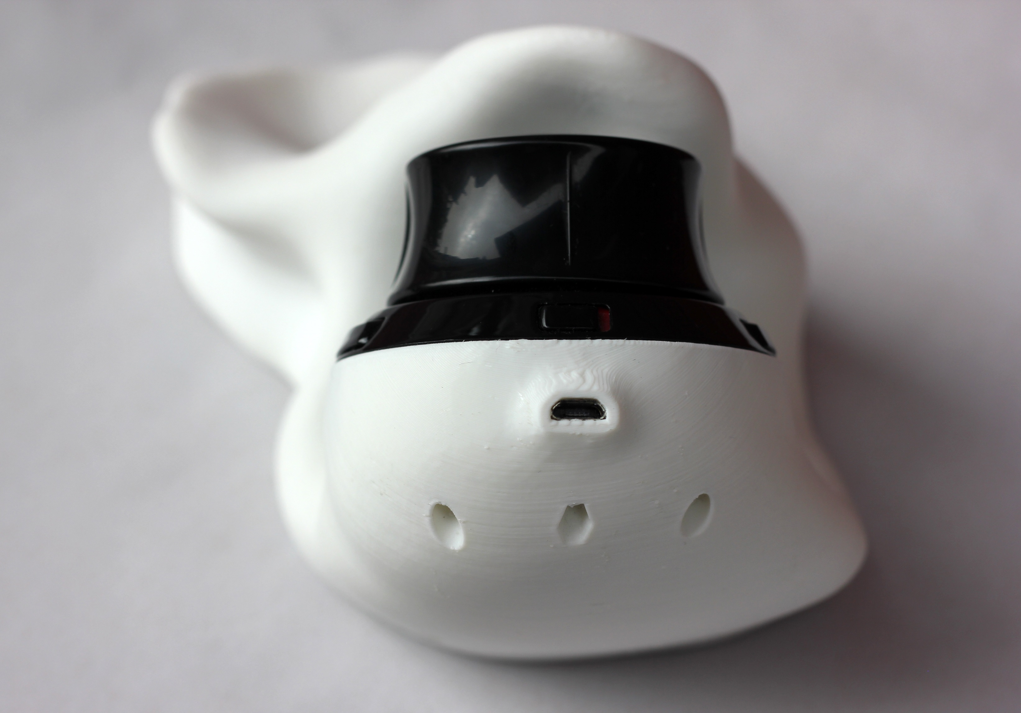
The USB connector is inconveniently positioned. It needs to be relocated closer to the device’s base.
Solving version 0 issues
So, problem number one is the weight of the base. Unfortunately, I couldn’t find metal shavings for sale to use them as described in the previous paragraph to add weight. Instead, I decided to use 6mm diameter steel balls for that purpose. As for epoxy resin, I ultimately opted out due to potential toxicity concerns, and instead used a two-component food-safe silicone.
A sample of the resulting “composite” material:

Next, to put the weight inside, it was necessary to make the base hollow or partially hollow. Initially, I leaned towards the second option, but then realized that the first option was better in many respects. Unfortunately, SolidWorks wasn’t suitable for this purpose; it already struggles with solid bodies derived from meshes, and performing a shell operation on such a body proved to be an insurmountable task. Meshmixer came to the rescue. An interesting detail: if you simply make the body hollow by removing all the material, leaving only the walls, the result will be two separate meshes. To prevent this, you need to create at least one hole in those walls, which Meshmixer can do automatically.
Now that the base is hollow on the inside, it needs to be made disassemblable to access the interior. I decided to use screws and embedded nuts to assemble the parts.
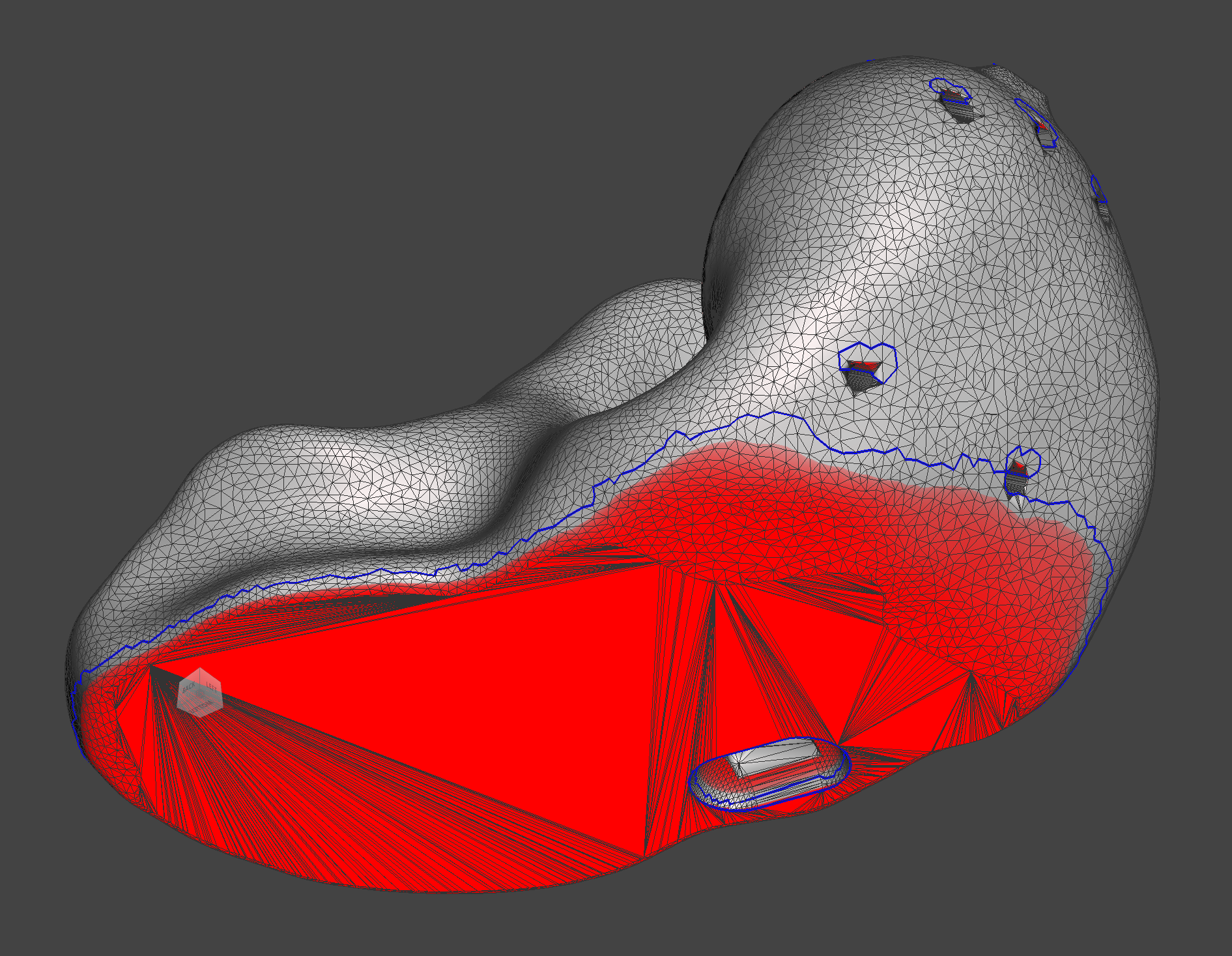
Finally, I optimized the external surface of the base to ensure that the overhang angle exceeded 45 degrees everywhere. Otherwise, the slicer generates external support structures, which mar the appearance even if they are printed with a different material. Here’s how it looked before (areas with an overhang angle less than 45 degrees are highlighted in red):
After the optimization:
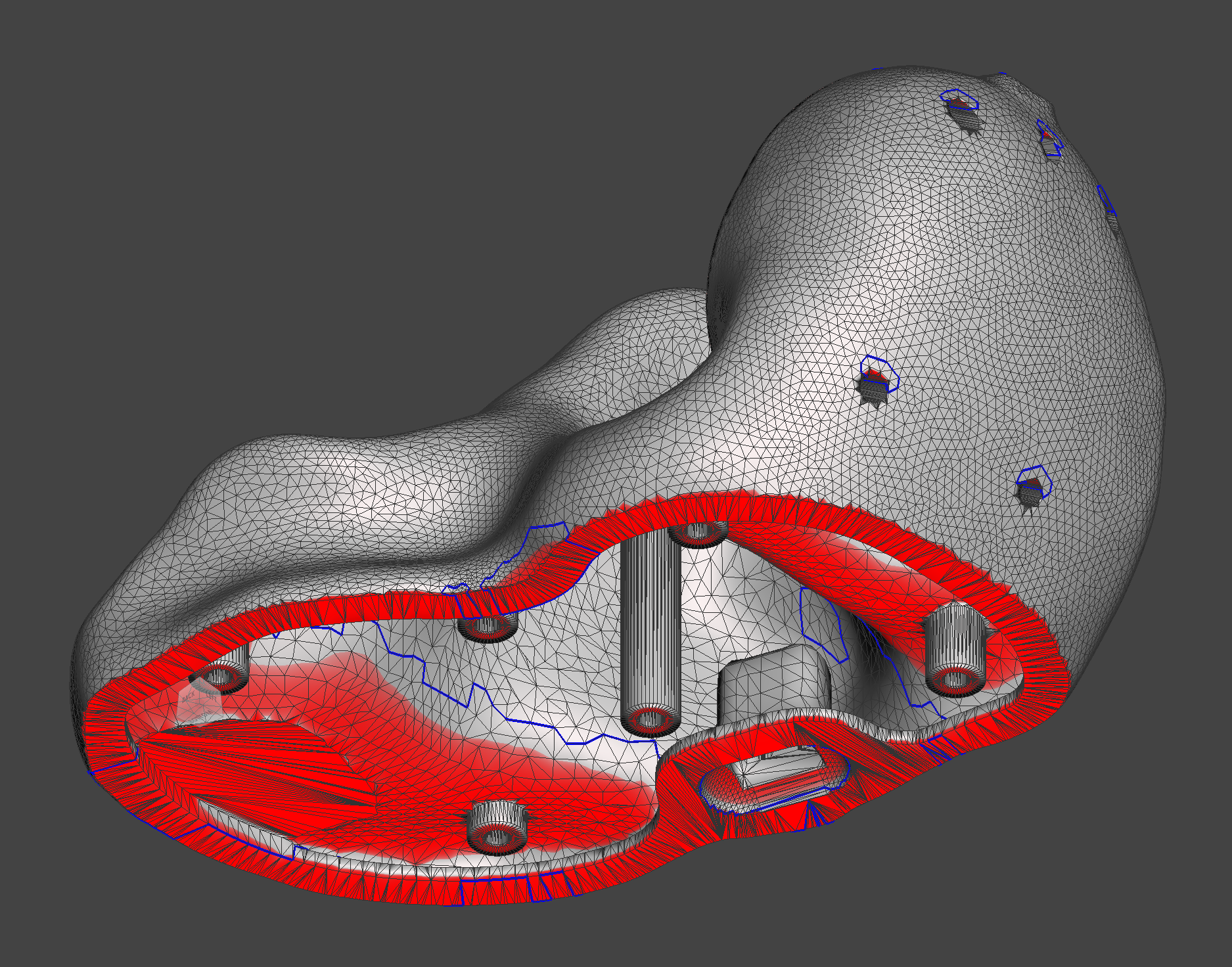
Final meshes of the base and the cover:
Version 1
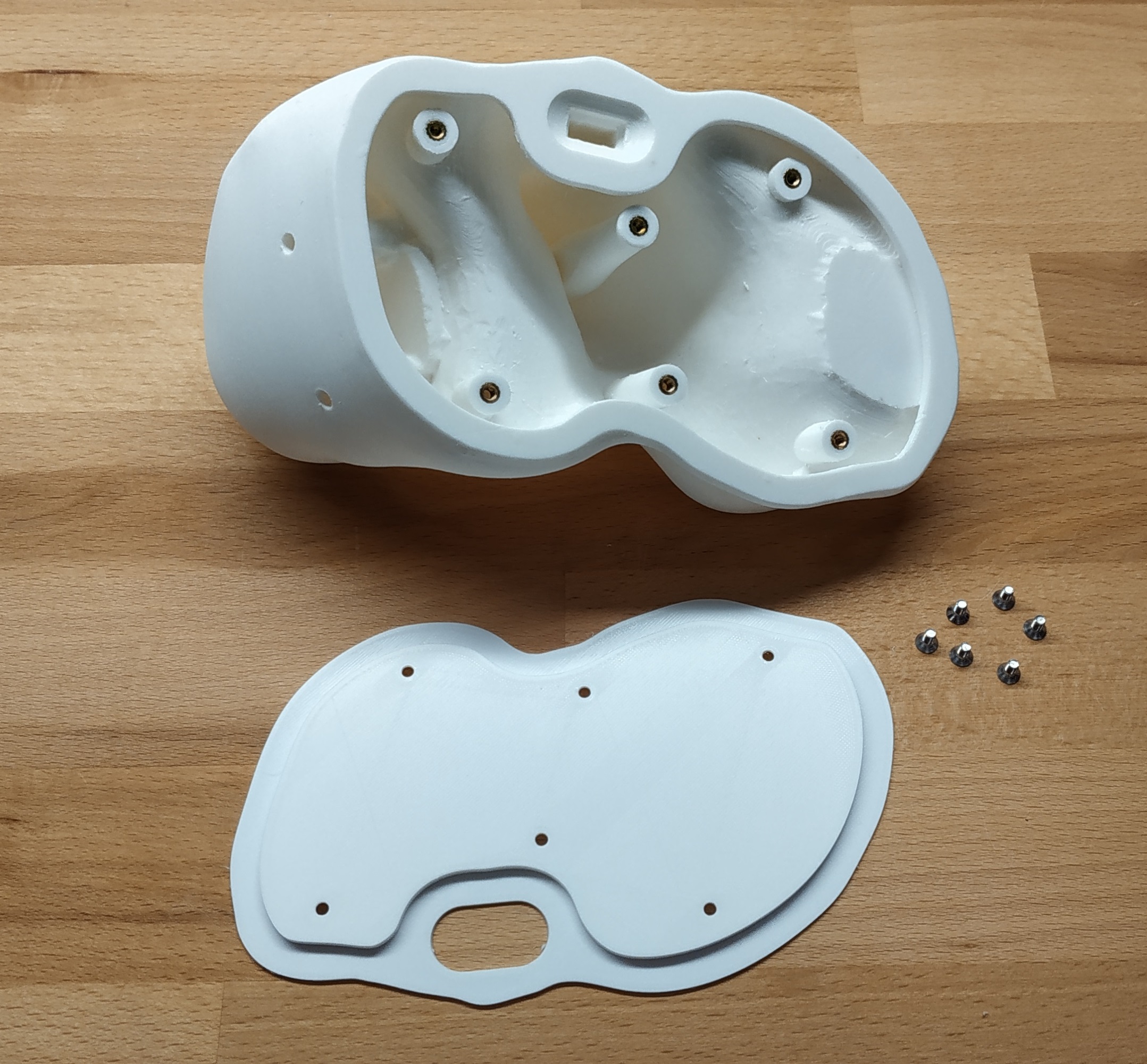
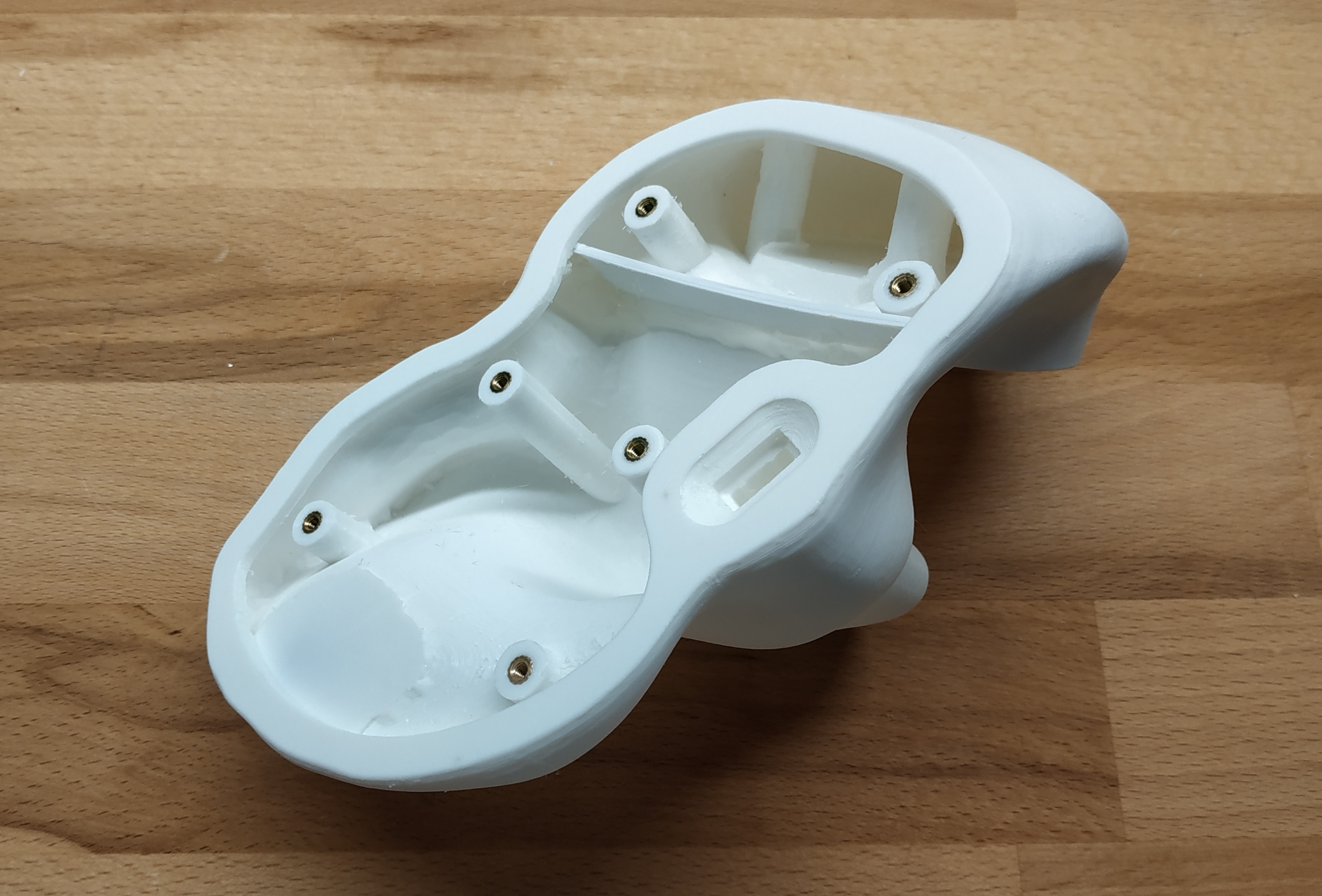
Printed the base and the cover, installed the embedded nuts:

Installed the plastic “formwork” for pouring the filler:
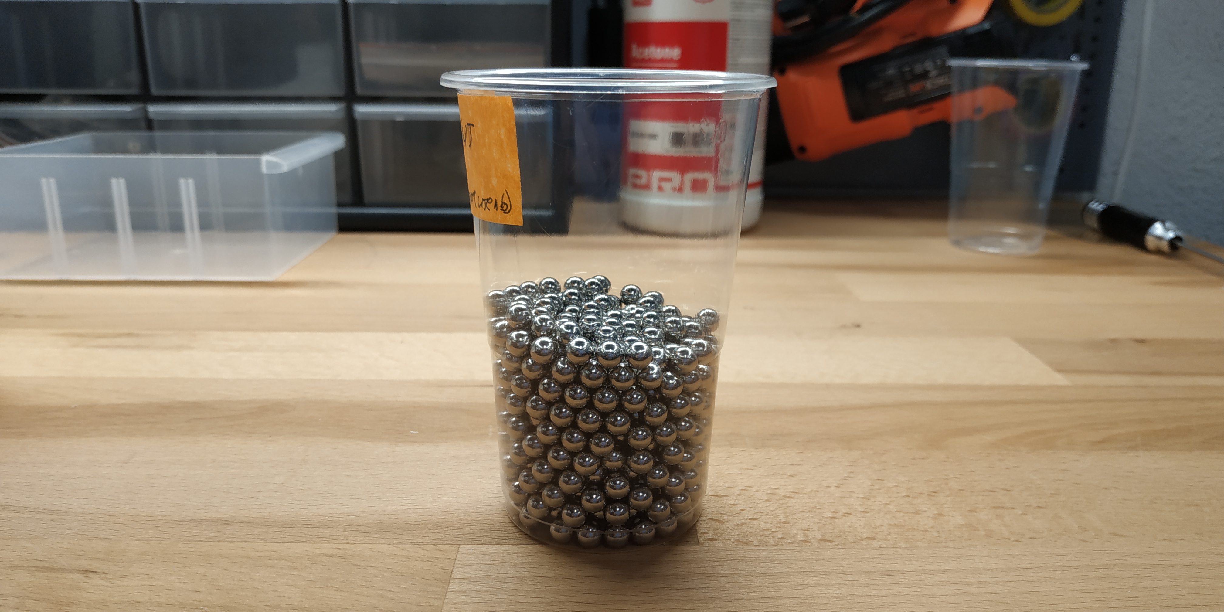
Selected the appropriate number of steel balls:
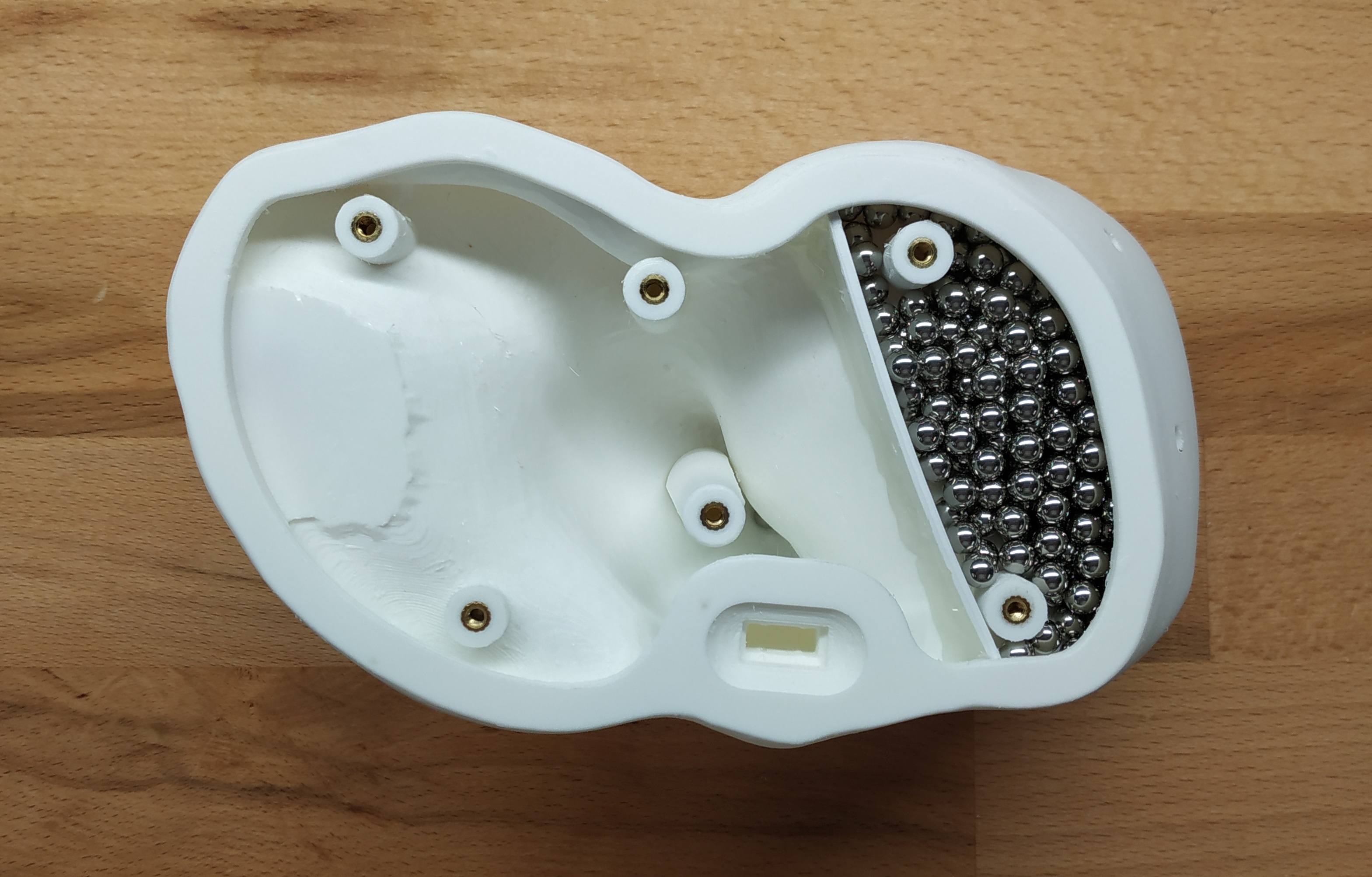
In total, this amount of steel balls was needed for the front part of the base:
Mixed the silicone in the required proportion, added the steel balls, placed the resulting mixture inside the base. Waited for the silicone to cure. The result:

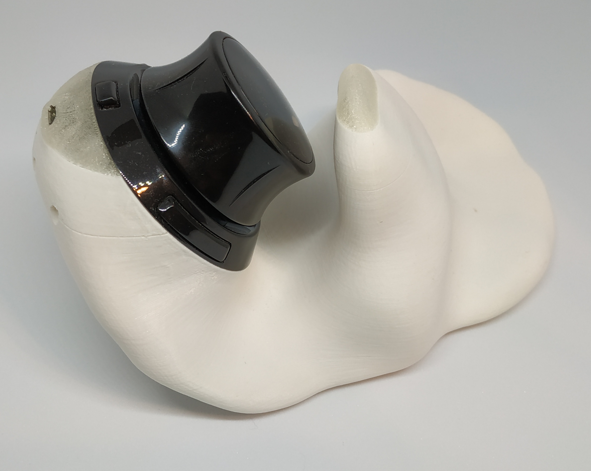
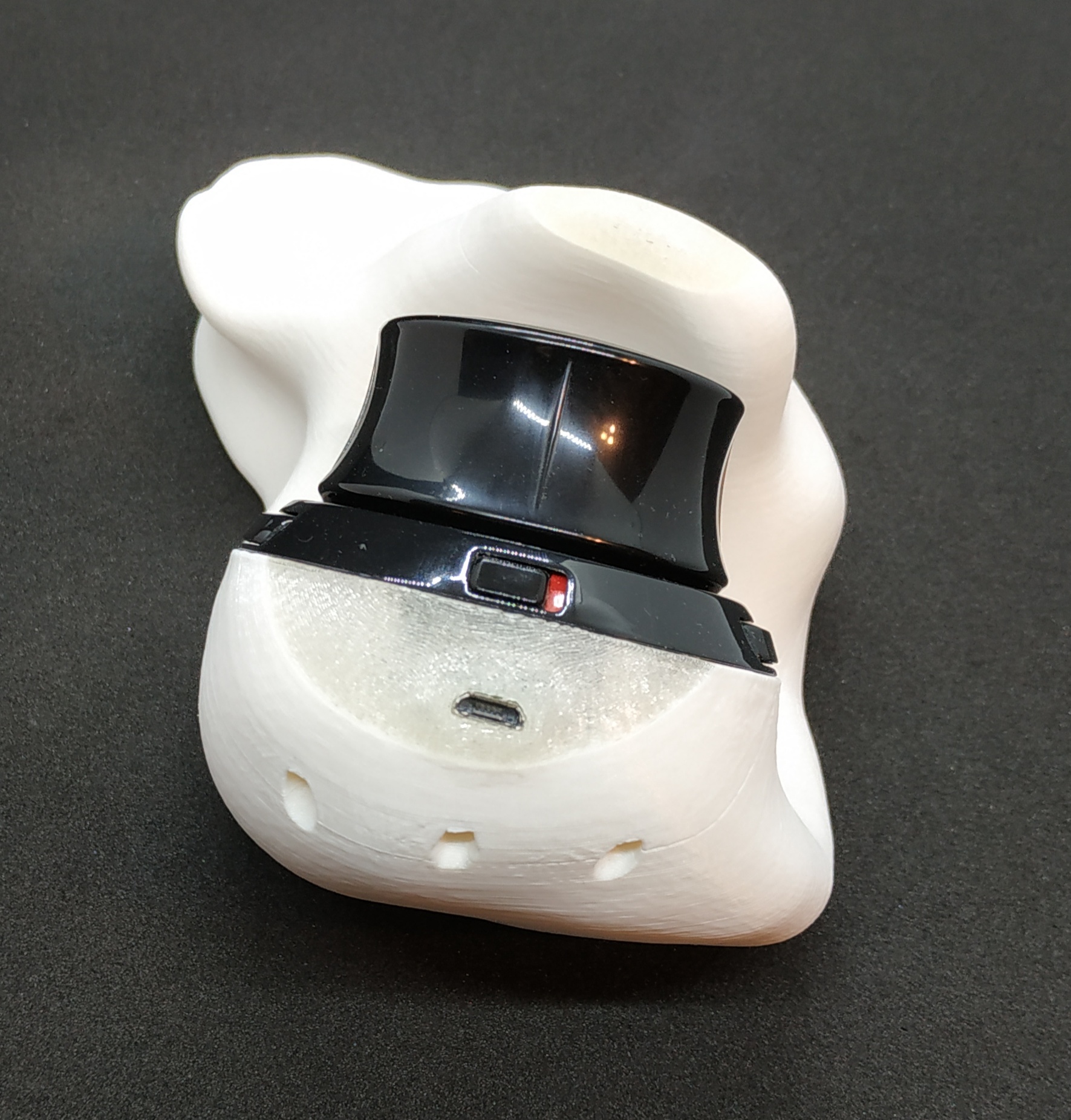
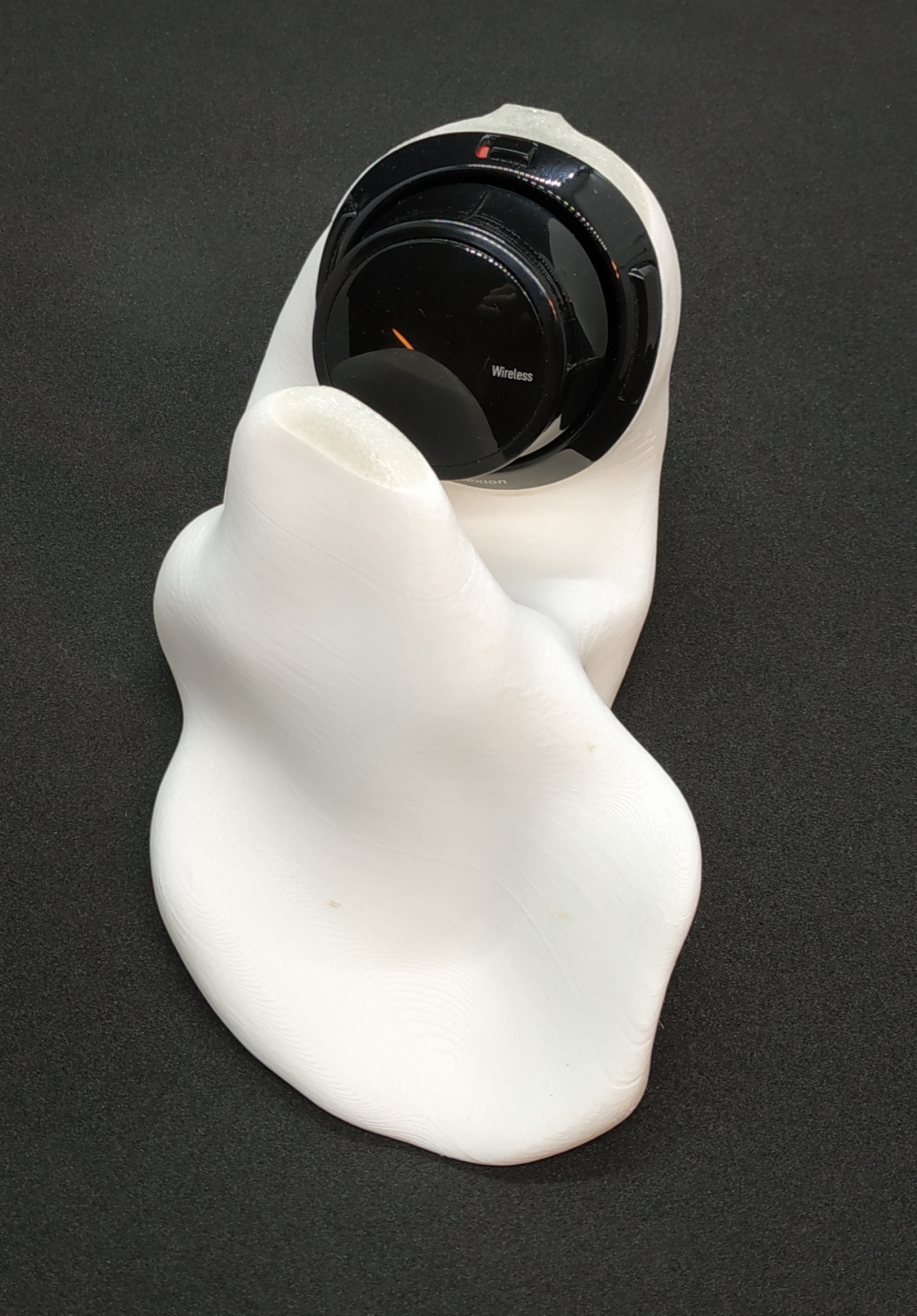
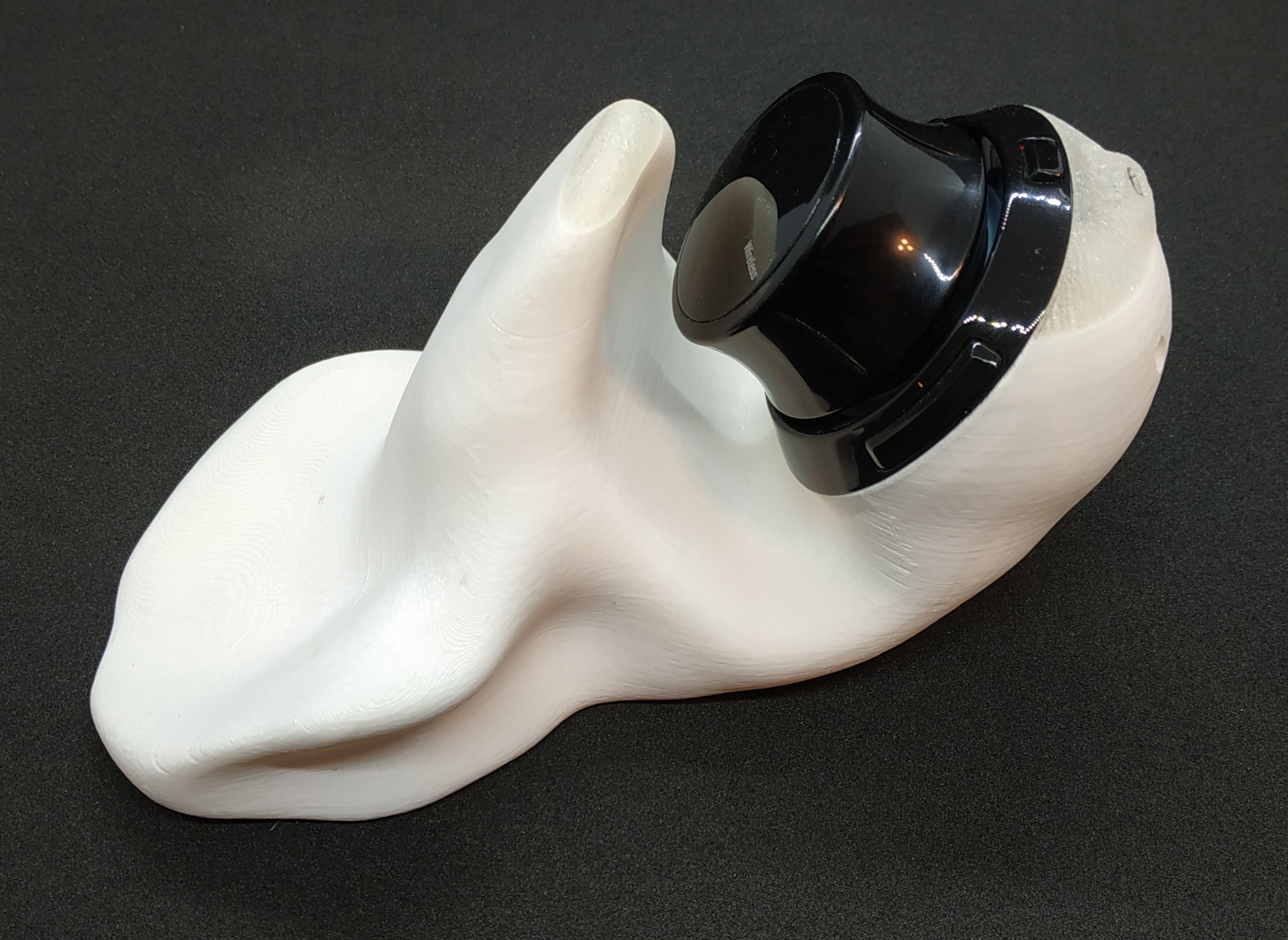
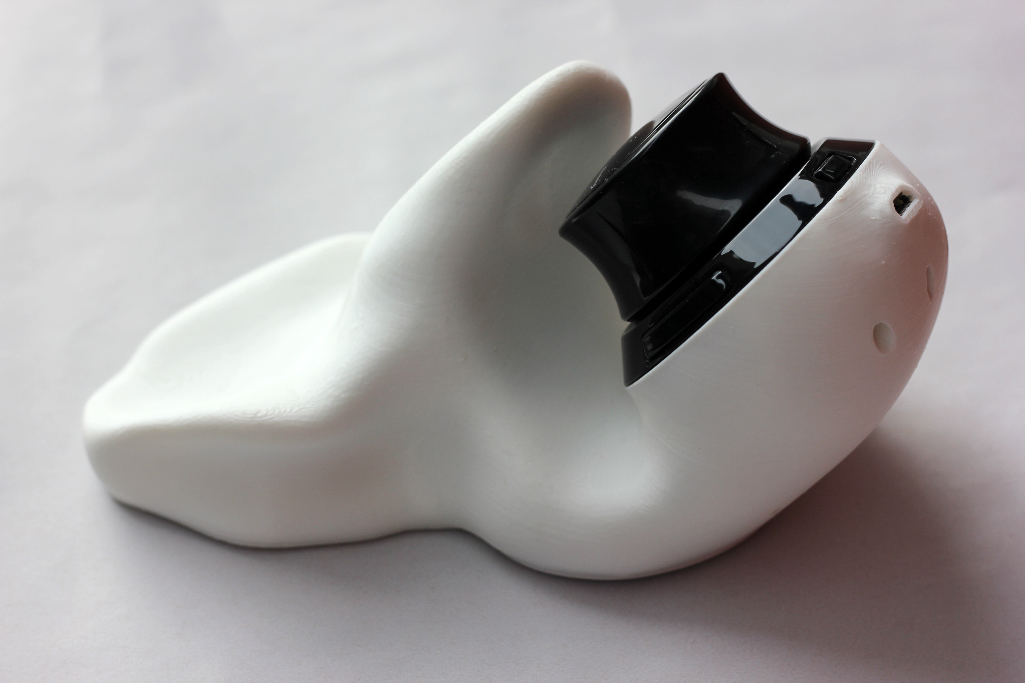
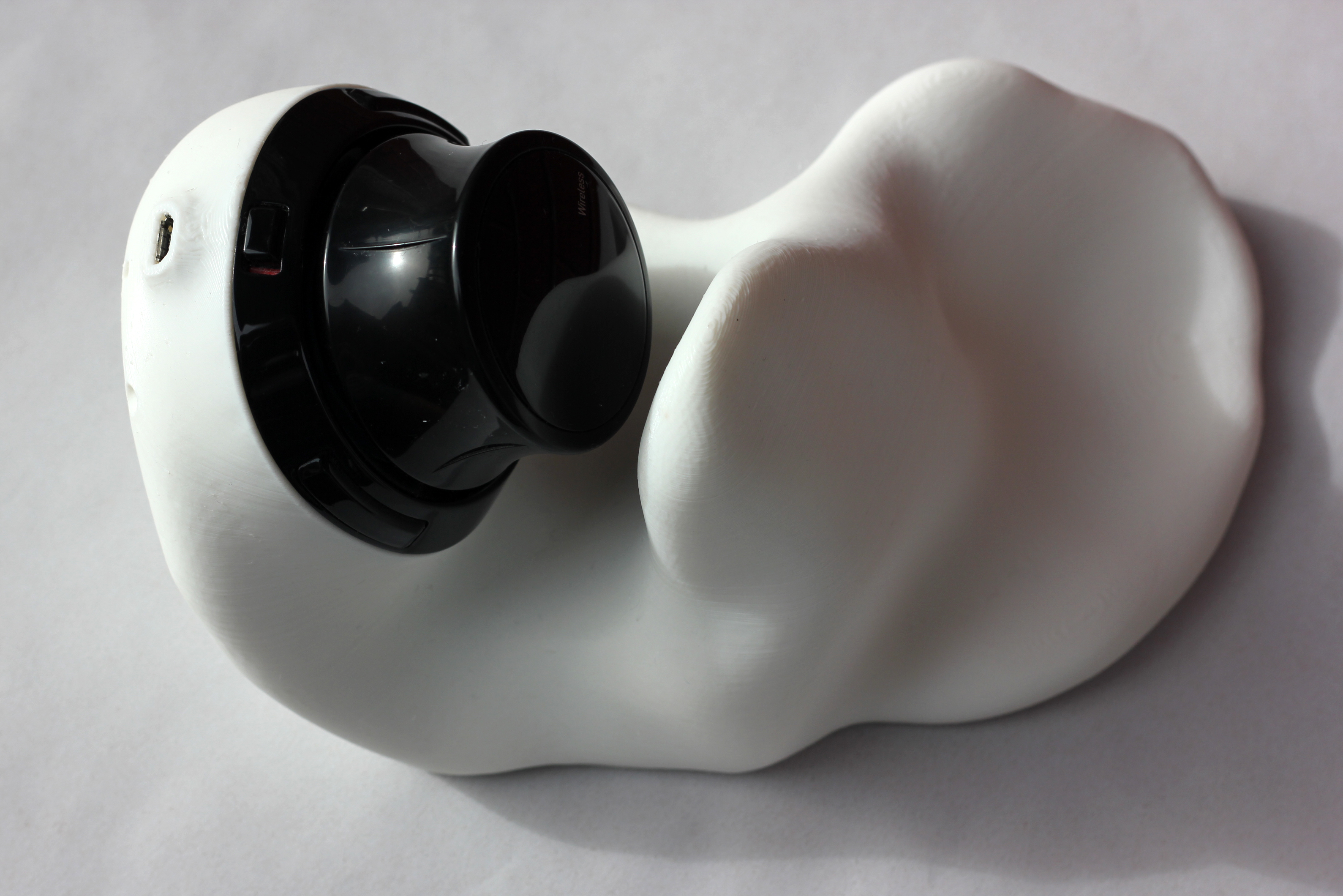
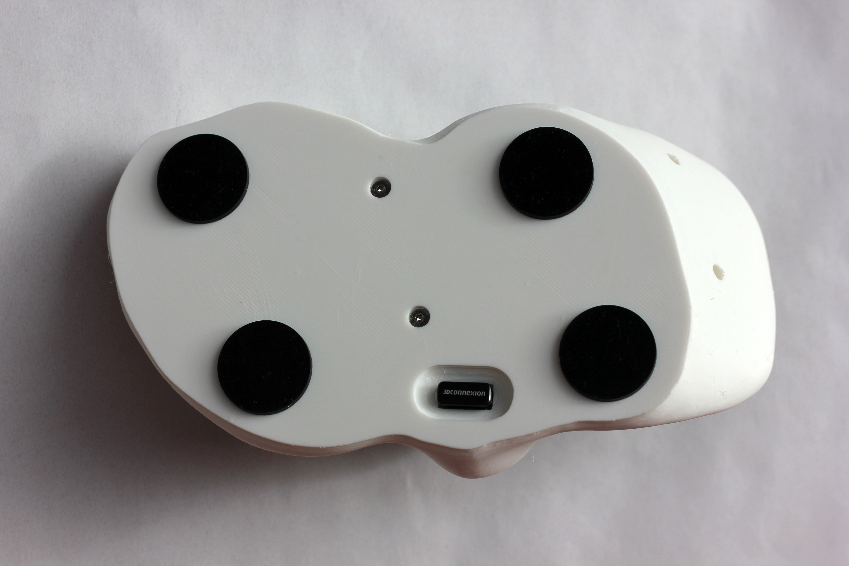
Placed the cover in position, screwed it in place. Attached the knob. Added the rubber feet. The final result:


Final renders